In this article I share my experience upgrading the 4-channel Motorola GM350 for use in digital nodes and repeaters.
Why the mod is needed
Unlike the Motorola GM340 or the 128-channel GM350, the 4-channel version does not bring all signals out to the accessory connector: Motorola cut costs on it by leaving some components unpopulated. That is what this guide fixes. There are several modifications around the internet; I tried a few of them and settled on the one described below.
Choosing the radio
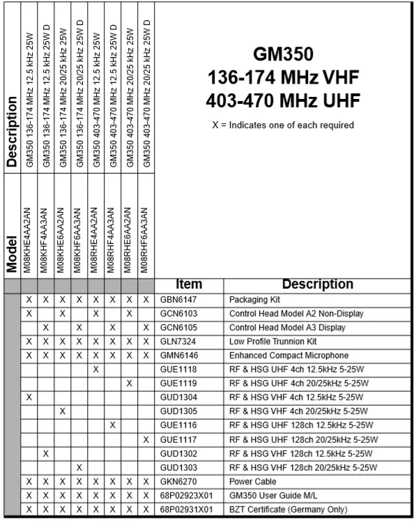
When choosing a radio: D-STAR needs the 12.5 kHz IF bandwidth version, while DMR and C4FM need the 25 kHz version. If you use a 12.5 kHz unit for C4FM, you will have to add an op-amp with a gain of 2 to the TX path and set the TX deviation limit to maximum in the radio menu. Check the model table below:
Modification
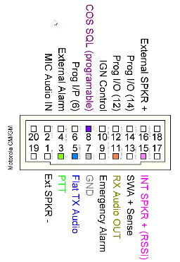
We need the following signals:
- Pin 3 --- PTT
- Pin 5 --- FLAT TX AUDIO
- Pin 11 --- RX AUDIO OUT
- Pin 8 --- COS SQL
- Pin 15 --- INT SPKR + (RSSI)
- Pin 10 --- IGN Control
Pin 10
Inside the radio, connect this pin to the +12 V supply input. The radio will then switch on by itself whenever power returns.
Pin 8
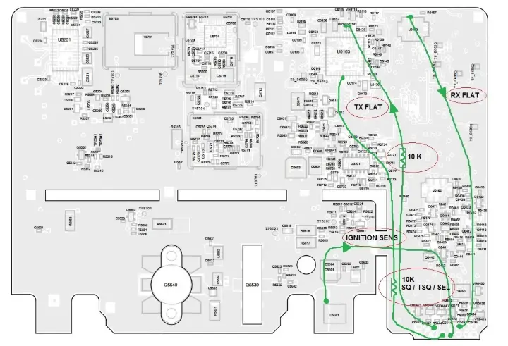
The squelch-open (COR) signal is taken from the main audio amplifier enable line, so in the CPS programming software tie it to SQ/TSQ/Selective.
Pins 3, 15
PTT and RSSI are normally already wired on the board and need no changes.
Pins 5 and 11
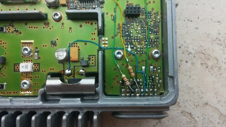
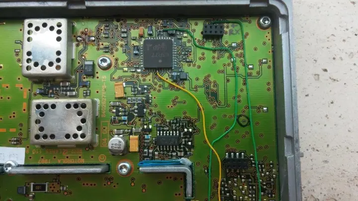
Wire pins 5 and 11 as shown in the diagram below, through 10 kΩ resistors.
Frequency drift on transmit
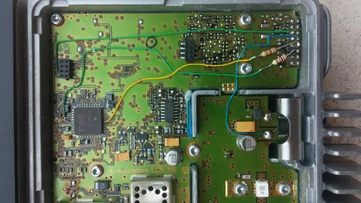
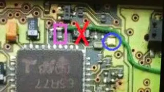
If the frequency drifts by a couple of kHz on TX, change the connection point — see Fig. 5 below.
Blue circle — the new connection point.
Red cross — remove the 3.3 µF capacitor.
Pink square — remove the resistor or replace both resistors with 1 kΩ.
DC-blocking capacitor
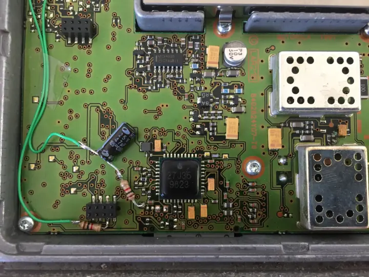
If the TX path of your radio modem has no coupling capacitor — and you will notice at once (no modulation on transmit, or the carrier amplitude wandering on the spectrogram) — you can add one right inside the radio. I recommend a 47 µF / 25 V electrolytic, see Fig. 6 below.
Checking the wiring
To check the wiring:
Disconnect the MMDVM from the radio and key the radio (TX).
Note the carrier frequency with an SDR receiver.
Connect the MMDVM to the radio and key it with MMDVMCal. Make sure the spectrum does not move in frequency or amplitude. If the carrier drifts, add the capacitor.
Calibration
RX level
No RX level calibration is needed. Turn the RX level control (if fitted) to maximum and set RXLevel=100 in the MMDVM settings.
TX level
TX level calibration means setting the transmitter deviation to 2.75 kHz. Recommended deviation values:
- D-STAR: ~1.2 kHz
- DMR: ~2.75 kHz
- C4FM: ~4.5 kHz
A detailed description of the calibration is here. It is easy: all you need is any RTL-SDR receiver.